Managing large computer networks efficiently requires organization. Imagine trying to manage hundreds or thousands of devices as one giant group! This is where subnetting comes in. So, what is a subnet? Simply put, a subnet (or subnetwork) is a smaller, logical division created within a larger IP network. It works hand-in-hand with IP addresses and a crucial component called the subnet mask. This guide will clearly explain subnetting concepts for anyone working with or learning about networks.
What is a Subnet (or Subnetwork)?
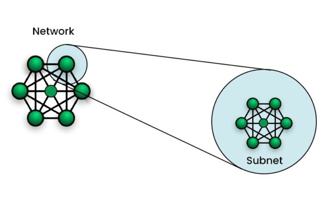
A subnet, or subnetwork, is a logically separate segment of a larger IP network. Think of your main network as a large plot of land defined by a single address range. Subnetting is like dividing that land into smaller, individual lots, each with its own specific boundary within the larger property.
Computers and other devices belonging to the same subnet share an identical initial sequence of bits in their IP addresses. This shared sequence, known as the network prefix, identifies the specific subnet they belong to. This logical grouping is key to how networks are structured and managed efficiently.
While the devices might be physically connected to the same switches, the logical separation created by subnetting controls how they communicate, especially regarding broadcast traffic and routing to external networks. It allows administrators to create distinct network zones within a larger allocated IP address space.
The Office Building Analogy
Imagine a large office building representing your entire network address space (e.g., all addresses starting with 192.168.1.x). Without subnetting, everyone is on the same floor, leading to noise and congestion. Subnetting is like dividing the building into different floors or departments (subnets).
Each department (subnet) has its own defined space. People within the same department can communicate easily. However, to communicate with someone in a different department (another subnet), they need to go through designated pathways or intermediaries (routers). This organization improves communication flow and security within the building.
Why Do We Use Subnetting? (Key Benefits)
Subnetting isn’t just an academic exercise; it provides tangible benefits that are crucial for the performance, security, and manageability of modern networks. Understanding these advantages clarifies why network administrators routinely implement subnetting in various environments, from small businesses to large enterprises and cloud deployments.
Improving Network Performance (Reducing Broadcast Traffic)
One of the primary benefits is reducing network congestion by limiting broadcast traffic. A broadcast message is sent from one device to all other devices within the same network segment. In large, flat networks (without subnets), broadcasts from many devices can flood the network, consuming bandwidth and processing power on every connected host.
Each subnet typically forms a separate broadcast domain. This means broadcast messages sent within one subnet are confined to that subnet and do not automatically propagate to others. By dividing a large network into smaller subnets, the impact of broadcast traffic is significantly reduced, leading to better overall network performance and responsiveness.
Enhancing Network Security (Isolation)
Subnetting allows administrators to implement network segmentation for security purposes. Different subnets can be created for different security zones, such as separating servers from workstations, guest Wi-Fi networks from internal corporate networks, or sensitive departments (like finance) from general office networks.
Traffic moving between these subnets must pass through a router. This router acts as a control point where security policies, such as firewall rules or Access Control Lists (ACLs), can be applied. These rules can permit or deny traffic flow between specific subnets, effectively isolating segments and limiting the potential impact of a security breach in one area.
For instance, if malware infects a device on a guest subnet, proper segmentation and firewall rules at the router connecting it to internal subnets can prevent the malware from spreading to critical internal systems. This isolation is a cornerstone of robust network security design.
Better Network Organization and Management
Subnetting provides a logical structure for organizing network resources. Administrators can assign specific subnets to different physical locations (buildings, floors), organizational units (departments like Marketing, Engineering, HR), or device types (servers, printers, VoIP phones, workstations).
This logical grouping simplifies various network management tasks. It makes troubleshooting easier by narrowing down the potential location of problems. It simplifies the application of specific network policies or Quality of Service (QoS) settings to particular groups of devices. It also aids in capacity planning and understanding network usage patterns.
More Efficient IP Address Use
While less critical with the vast address space of IPv6, efficient IP address allocation was a major driver for subnetting in the IPv4 world, especially with the limitations of the old classful addressing system. Subnetting allows an organization to take a large block of assigned IP addresses and divide it appropriately among different segments.
Instead of assigning a large, potentially wasteful block to a small department, subnetting allows the creation of smaller address ranges tailored to the actual number of devices needing addresses in that segment. This prevents the exhaustion of available IP addresses and allows for more granular control over allocation within an organization’s assigned address space.
The Key: Understanding IP Addresses and Subnet Masks
To grasp subnetting, you must first understand how IP addresses and subnet masks work together. An IP address (specifically IPv4 for now) is a unique 32-bit number assigned to each device on a network, typically written in dotted-decimal format (e.g., 192.168.1.10).
This 32-bit address isn’t just a single identifier; it’s logically divided into two parts:
- Network Portion: The initial part of the address identifies the specific network the device belongs to. All devices on the same network share the same network portion.
- Host Portion: The remaining part of the address identifies the specific device (host) within that network. This part must be unique for each device on the same network.
The Subnet Mask is the crucial element that tells devices and routers where this division between the network portion and the host portion occurs for any given IP address. It’s also a 32-bit number, usually written in dotted-decimal format like an IP address.
In its binary form, a subnet mask consists of a continuous sequence of ‘1’s followed by a continuous sequence of ‘0’s.
- The positions with ‘1’s in the mask correspond to the Network Portion of the IP address.
- The positions with ‘0’s in the mask correspond to the Host Portion of the IP address.
For example, the common subnet mask 255.255.255.0 translates to binary: 11111111.11111111.11111111.00000000 This mask indicates that the first 24 bits (three octets) of an associated IP address define the network, and the last 8 bits (one octet) define the host.
How the Subnet Mask Creates Subnets
Subnetting fundamentally involves extending the network portion of the address by “borrowing” bits that were originally part of the host portion. This is done by changing some of the leading ‘0’s in the host part of the subnet mask to ‘1’s.
For example, changing the mask from 255.255.255.0 (...00000000) to 255.255.255.128 (...10000000) borrows one bit from the host portion for the network/subnet portion. This single borrowed bit allows you to create two distinct subnets (one where the borrowed bit is 0, one where it’s 1) from the original single network.
The subnet mask is therefore essential. Devices use it (via a binary AND operation with the IP address) to determine their own network address and to determine if a destination IP address is on the same local network or if it needs to be sent to the default gateway (router) for forwarding.
Introducing CIDR Notation
Writing out full subnet masks like 255.255.255.0 or 255.255.240.0 can be cumbersome. The modern and standard way to represent network addresses and their associated masks is CIDR (Classless Inter-Domain Routing) notation. CIDR was introduced primarily by RFC 4632 to overcome the limitations of the old classful addressing scheme.
CIDR notation appends a forward slash (/) followed by a number to the IP address. This number, called the prefix length, simply represents the count of consecutive leading ‘1’ bits in the subnet mask. It directly indicates how many bits are part of the network portion (including any subnet bits).
Here are some common examples:
192.168.1.0 /24means the first 24 bits define the network. This corresponds to the mask255.255.255.0.10.0.0.0 /8means the first 8 bits define the network. This corresponds to the mask255.0.0.0.172.16.0.0 /16means the first 16 bits define the network. This corresponds to the mask255.255.0.0.192.168.1.0 /25means the first 25 bits define the network. This corresponds to the mask255.255.255.128.
Reading CIDR Notation
Understanding CIDR notation is crucial for modern networking. The prefix length directly tells you the size of the network portion and, by subtraction (32 – prefix length), the size of the host portion. This determines the number of possible IP addresses within that network or subnet.
CIDR offers significant advantages:
- Conciseness:
/24is much easier to write and read than255.255.255.0. - Flexibility: It enables Variable Length Subnet Masking (VLSM), allowing administrators to create subnets of different sizes from a single block, matching the specific needs of each network segment more precisely.
- Efficiency: CIDR facilitates route aggregation (supernetting), where multiple smaller network prefixes can be summarized into a single larger prefix, significantly reducing the size of routing tables on the internet and improving routing efficiency.
The transition from classful addressing (fixed masks for Class A, B, C) to classless addressing with CIDR was essential for scaling the internet and conserving IPv4 addresses. All modern network configurations use CIDR notation.
How Subnetting Actually Works
Subnetting achieves its benefits through specific technical mechanisms related to how network devices handle addressing and communication within these logical segments. Understanding these mechanics clarifies the practical impact of creating subnets.
Creating Logical Network Segments
As established, subnetting uses the subnet mask or CIDR prefix to divide a larger IP address range into smaller, distinct ranges. Each of these smaller ranges represents a unique subnet. All devices configured with IP addresses belonging to the same subnet range are considered part of that logical network segment.
For example, if 192.168.1.0/24 is divided into two /25 subnets (192.168.1.0/25 and 192.168.1.128/25), a device with IP 192.168.1.50 belongs to the first subnet, while a device with IP 192.168.1.150 belongs to the second subnet, even if they are physically connected to the same network switch.
Defining Broadcast Domains
A key consequence of this logical segmentation is the creation of separate broadcast domains. A broadcast domain encompasses all devices that will receive a broadcast frame sent by any one device within that domain. Routers, by default, do not forward broadcast traffic between the networks (or subnets) they connect.
Therefore, each subnet typically constitutes its own broadcast domain. When a device sends a broadcast message (e.g., an ARP request to find a MAC address), only the devices within its own subnet receive and process that message. Devices in other subnets are unaffected. This containment is crucial for reducing unnecessary network traffic and CPU load on devices.
The Role of Routers in Connecting Subnets
Since devices on different subnets belong to logically separate networks, they cannot communicate directly using Layer 2 switching alone. For a device in Subnet A to send data to a device in Subnet B, the traffic must be forwarded by a router.
The sending device recognizes (using its IP address and subnet mask) that the destination IP is on a different subnet. It then sends the packet to its configured default gateway (which is typically a router interface connected to its subnet). The router receives the packet, consults its routing table to find the path to the destination subnet, and forwards the packet accordingly, often out another interface connected to the destination subnet or towards another router closer to it. Routers are therefore essential for inter-subnet communication.
Subnetting Example: Breaking Down a Network
Let’s walk through a practical example to solidify understanding. Suppose an organization is assigned the private network block 192.168.10.0 /24. This gives them one network with 254 usable host addresses (from .1 to .254).
- Network Address:
192.168.10.0 - Subnet Mask:
255.255.255.0(/24) - Broadcast Address:
192.168.10.255 - Usable IPs:
192.168.10.1–192.168.10.254(2<sup>8</sup> – 2 = 254 hosts)
Now, imagine they need to create four separate network segments for different departments (Sales, Marketing, Engineering, Support), each needing around 50 devices. Subnetting the /24 block is the solution. To get at least four subnets, we need to borrow bits from the host portion. Borrowing 2 bits (2<sup>2</sup> = 4 subnets) seems appropriate.
Original host bits: 8 (00000000) Borrowing 2 bits means the new network portion will be 24 + 2 = 26 bits long. The new prefix length is /26. New subnet mask in binary: 11111111.11111111.11111111.11000000 New subnet mask in dotted-decimal: 255.255.255.192
The remaining host bits are now 8 – 2 = 6 bits.
Calculating Usable IPs (The Concept)
With 6 host bits, each subnet will have 2<sup>6</sup> = 64 total addresses. Since the first address is the Network Address and the last is the Broadcast Address, the number of usable host IPs per subnet is 64 – 2 = 62. This meets the requirement of ~50 devices per department.
The four resulting subnets are:
Subnet 1 (Sales):
- Network Address:
192.168.10.0 /26 - Usable Host Range:
192.168.10.1–192.168.10.62 - Broadcast Address:
192.168.10.63
Subnet 2 (Marketing):
- Network Address:
192.168.10.64 /26 - Usable Host Range:
192.168.10.65–192.168.10.126 - Broadcast Address:
192.168.10.127
Subnet 3 (Engineering):
- Network Address:
192.168.10.128 /26 - Usable Host Range:
192.168.10.129–192.168.10.190 - Broadcast Address:
192.168.10.191
Subnet 4 (Support):
- Network Address:
192.168.10.192 /26 - Usable Host Range:
192.168.10.193–192.168.10.254 - Broadcast Address:
192.168.10.255
This example shows how subnetting divides the original /24 block into four distinct /26 subnets, each with its own address range, network ID, and broadcast ID, allowing for logical separation and management. A router would be needed to allow communication between these departments.
Subnets vs. VLANs: What’s the Difference?
Subnets are often discussed alongside VLANs (Virtual Local Area Networks), as both are methods for segmenting networks. However, they operate at different layers of the networking model and achieve segmentation differently. Understanding the distinction is important for network design.
Subnets operate at Layer 3 (Network Layer) of the OSI model. Segmentation is based on IP addressing and subnet masks. Each subnet represents a distinct IP network or subnetwork. Communication between different subnets requires a Layer 3 device, typically a router, to forward packets based on IP addresses.
VLANs operate at Layer 2 (Data Link Layer) of the OSI model. Segmentation is achieved using network switches that support VLAN tagging (like IEEE 802.1Q). Devices are assigned to specific VLANs (e.g., VLAN 10, VLAN 20), and switches ensure that broadcast traffic and direct Layer 2 communication are confined within that VLAN, regardless of the devices’ physical location on the switch infrastructure. Communication between different VLANs also requires a Layer 3 router (often called inter-VLAN routing).
In practice, subnets and VLANs are frequently used together. A common best practice is to assign each VLAN its own unique IP subnet. For example, VLAN 10 might be assigned the subnet 192.168.10.0/24, while VLAN 20 uses 192.168.20.0/24. This aligns Layer 2 broadcast domains (VLANs) with Layer 3 logical networks (subnets), simplifying management and routing.
Subnets in the Cloud (VPCs)
The concept of subnetting is absolutely critical in modern cloud computing. Platforms like Amazon Web Services (AWS), Microsoft Azure, and Google Cloud Platform (GCP) allow users to create Virtual Private Clouds (VPCs) – logically isolated sections of the public cloud where they can launch resources.
Within a VPC, subnets are the fundamental mechanism for segmenting the virtual network. When you create a VPC, you define a large IP address range (using CIDR notation). You then divide this range into multiple subnets, typically distributing them across different Availability Zones (isolated physical data centers within a region) for high availability.
Cloud subnets serve several key purposes:
- Resource Placement: You launch resources like virtual machines (EC2 instances), databases (RDS), and load balancers into specific subnets.
- Access Control: Security rules (like AWS Security Groups or Azure Network Security Groups) and network ACLs are often applied at the subnet level or to instances within specific subnets to control traffic flow.
- Public vs. Private: You typically designate subnets as either “public” (with a route to an internet gateway, allowing direct internet access) or “private” (no direct internet route, often accessing the internet via NAT gateways or used for backend systems). This creates tiered security architectures.
Understanding how to design and manage subnets within a VPC is essential for building secure, scalable, and highly available applications in the cloud. The principles are the same as traditional networking, but the implementation occurs within the cloud provider’s software-defined networking environment.
A Note on IPv6 Subnetting
While most examples focus on IPv4 due to its historical prevalence and tighter address constraints, subnetting is also fundamental to IPv6 networking. The core concepts remain the same – dividing a larger address prefix into smaller ones – but the scale is vastly different due to IPv6’s 128-bit addresses.
A typical IPv6 allocation to an organization or site is a /48 prefix, providing an enormous amount of address space (2<sup>80</sup> addresses). Standard practice and RFC recommendations strongly advise subnetting this allocation using a /64 prefix length for individual network segments (like LANs).
Using a /64 prefix means the first 64 bits identify the network/subnet, and the remaining 64 bits identify the host interface. This large host portion (2<sup>64</sup> possible addresses per subnet) is intentional. It simplifies network management and enables features like Stateless Address Autoconfiguration (SLAAC), where devices can automatically generate their own unique host address based on the /64 network prefix advertised by the local router, without needing DHCP for basic addressing.
While technically possible to use prefixes longer than /64 for point-to-point links or specific cases, /64 is the standard for end-user network segments in IPv6. The sheer abundance of addresses means the focus shifts from conserving addresses (as in IPv4 subnetting) to logical organization and supporting IPv6’s built-in features.